Rinnai SUNMASTER Installation Manual Page 19
- Page / 64
- Table of contents
- BOOKMARKS
- Operation / Installation 1
- TABLE OF CONTENTS 3
- Twist cap until water 7
- Lift lever until water 7
- (Lower lever genlty!) 7
- IMPORTANT 8
- SAVE A SERVICE CALL 10
- SPECIFICATIONS FOR SYSTEMS 12
- (HPFTC- 8-10) 13
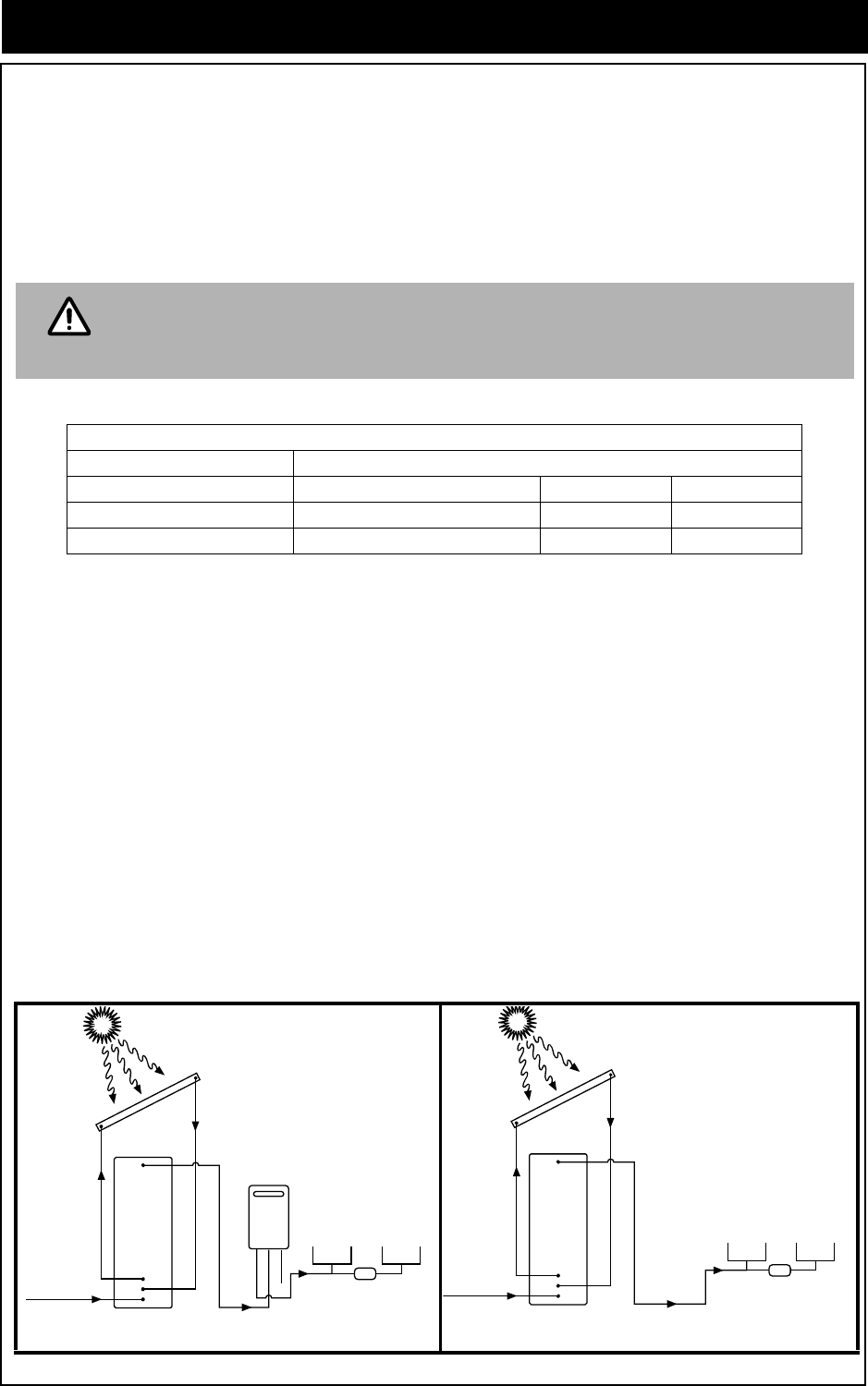
- Solar cold water inlet 19
- Solar hot water return 19
- • AS 5601 Gas Installations 21
- • AS/NZS 3000 Wiring rules 21
- STANDARD 22
- 1 collector : R33202739 23
- 2 collectors : R33202740 23
- 3 collectors : R33202741 23
- STANDARD INSTALLATION 24
- Nail strap to rafter 25
- Tiles removed 25
- REVERSE 27
- COMMERCIAL INSTALLATIONS 28
- HOT SENSOR SHEATH 30
- ON OUTLET OF ONE 30
- SET OF PANELS 30
- ENSURE COLLECTOR OPERATION 32
- CLEARANCES 34
- Items Supplied in SGPKIT 37
- Items Supplied with Cylinder 39
- Items Supplied in SGPKIT2 39
- Items Supplied in SGPKIT270 41
- Figure 30 42
- Items Supplied in SGPKIT3 43
- 7. Cold Water Supply 45
- 8. Relief Drain Lines 45
- 9. Hot Water Discharge 45
- 10. Connect Gas to Booster 45
- 10.500.50 46
- 21.251.25 46
- 32.102.10 46
- Items Supplied in SEPKIT 51
- Items Supplied in USKIT1 53
- 3. Connect PTR Valve 56
- 21.000.65 60
- 31.251.00 60
- NOTESNOTES 63
- CONTACT INFORMATION 64
Related products and manuals for Water heaters & boilers Rinnai SUNMASTER

 (84 pages)
© 2020, manymanuals.com. All rights reserved. | 2.568 s |
 Manymanuals.com
 Manymanuals.de
 Manymanuals.fr
 Manymanuals.it
 Manymanuals.pl
 Manymanuals.cz
 Manymanuals.es
 Manymanuals-pt.com
Comments to this Manuals